CO2 Laser Scanners are a very important part of a laser engraving or cutting machine. CO2 Laser Scanners are designed as a dynamic magnetic structure and play a huge role in the work of the engraving machine. Let’s learn more about the role of the co2 galvo laser.
Features of CO2 Laser Scanners
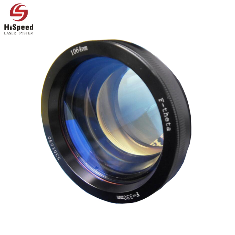
The galvo co2 laser is designed as a dynamic magnetic structure. It combines the most advanced international photoelectric type sensing technology and the PDM control method. Numerous features of the laser galvo scanner include strong anti-interference capabilities, excellent positioning precision, and exceptional operating stability. Its extensive performance indicators match the highest technological standard of comparable goods both domestically and internationally.
These specific qualities are included:
- The laser mirror scanner has its own intellectual property rights and imports its photoelectric sensors from the US.
- The differential photoelectric sensor of the CO2 laser scanner precisely determines the location of the motor rotor. It has good linearity, small drift, high resolution, and repeatable positioning accuracy.
- The galvo head co2 laser is designed to load the 10 mm lens precisely. The best dynamic properties of the system are guaranteed by a laser galvo scanner with high accuracy, logical construction, low static friction coefficient, and zero offsets.
- To assure the best dynamic properties of the system, the CO2 laser scanner is built with high precision, appropriate construction, low static friction coefficient, and zero offset.
- Overload, overcurrent, and reverse connection protection are included in the galvo co2 laser’s architecture, which increases system dependability.
- The system is built with robust anti-interference capabilities, a high signal-to-noise ratio, and electromagnetic compatibility optimization.
- Solve the co2 galvo laser marking machine temperature drift, signal interference, zero drift, and other common problems.
- It is easily integrated into a variety of application systems despite weighing only 1 kilogram.
CO2 laser scanner performance specifications
| Speed | ||
|---|---|---|
| Marking speed | 4000mm/s | |
| Positioning speed | 4000mm/s | |
| Writing speed | 301cps | |
| Step response time (1% of full travel) | 370us | |
| Step response time (10% of full travel) | 630us | |
| Tracking Error | ≤202us | |
Accuracy and error |
||
| Linearity | 99.9% | |
| Repeat positioning accuracy | <8μRad | |
| Gain error | <5mRad | |
| Zero point offset (batch origin error) | <5mRad | |
| Long drift (8 hours of continuous operation) | <0.5mRad | |
| Scale Drift | <40PPM/℃ | |
| Zero Drift | <15μRad/℃ | |
| Lens damage thresholds | ||
| K9 Substrate | 9.1J/cm^2 | |
| Si Substrate | 10J/cm^2 | |
| Lens reflective wavelength | 10600nm / 1064nm / 355nm | |
Power & Signal |
||
| Input Voltage | ±15VDC | |
| Average operating current | 2A | |
| Signal Interface | Digital | XY2-100 |
| Analog | ±5V | |
| Peak current | 8A | |
| Position signal input resistance | 10KΩ±1% | |
| Mechanical scanning angle | ±11° | |
Operating current, temperature, size |
||
| Operating temperature | 0℃─45℃ | |
| Storage temperature | -10℃─60℃ | |
| Laser input aperture | 10mm | |
| CO2 laser scanner size (L×W×H) | 118.5×96.5x94mm | |
| CO2 laser scanner weight | ≈1Kg |
Note: The above parameters are tested after 30min of warm-up
- Using the F-Theta lens with a focal length of 160mm, marking 2mm high single-line characters.
- Use an F-Theta lens with a focal length of 160mm, marking 1mm high single-line characters per second.
- Can custom special wavelength coating.
- The standard mechanical scanning angle is ±11°, the maximum mechanical scanning angle is ±15°, and if there are special needs can be customized.
What is the working principle of a CO2 laser?
Shape of the CO2 laser scanner holder
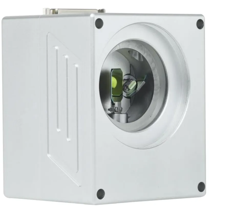
Dimensional diagram of the CO2 laser scanner holder
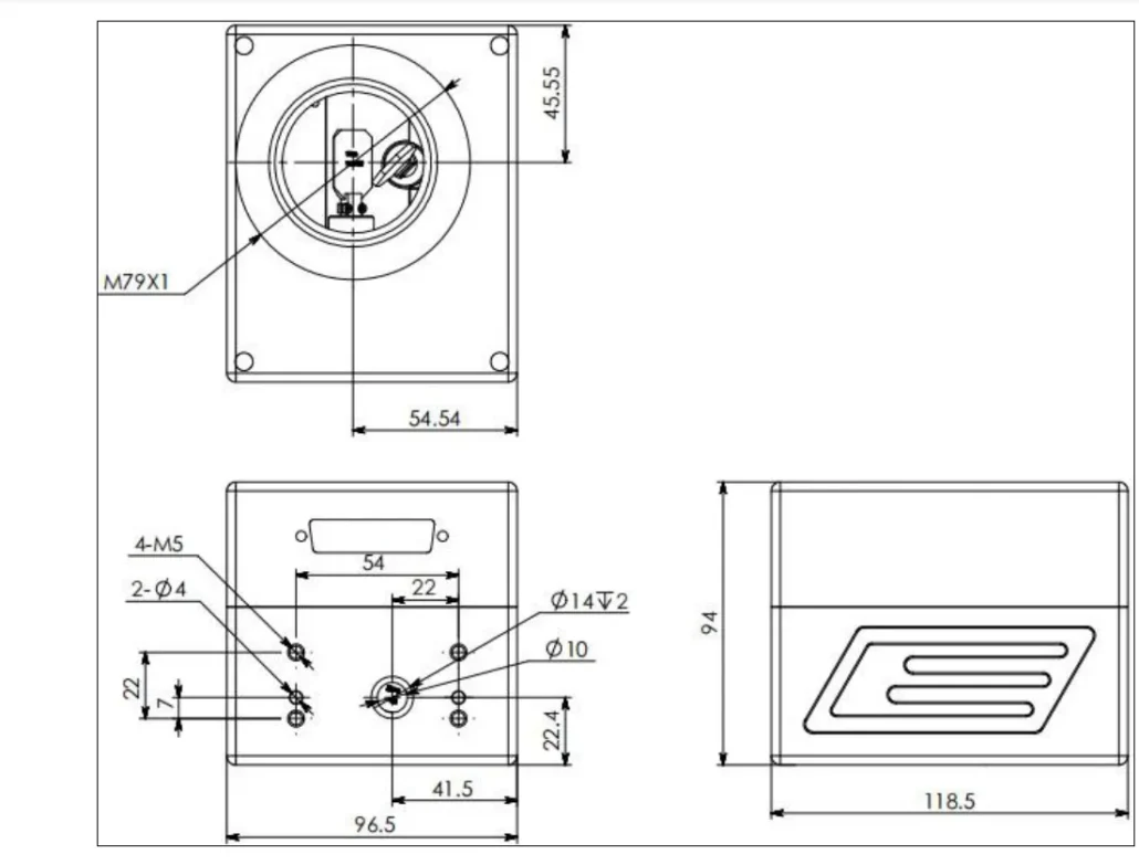
Power supply wiring diagram
Digital mirror external wiring definition diagram
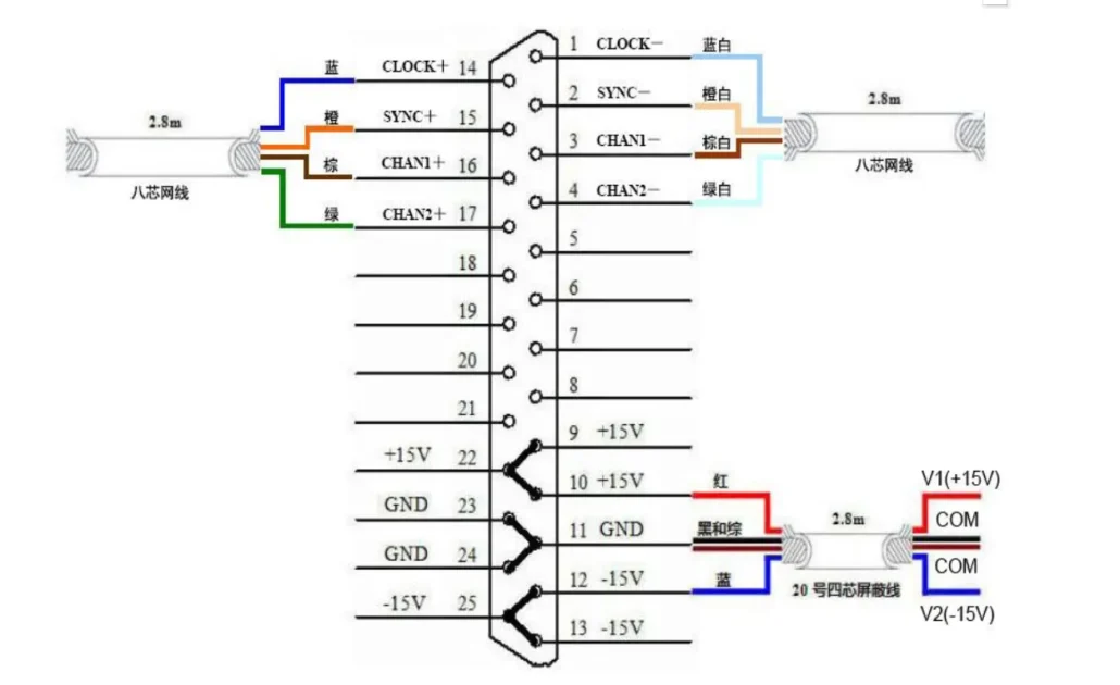
CO2 laser scanner common failures
Before powering on, check the whole system to see if there are false plugs, missing plugs, lenses touching each other, wrong drive signal, and power input.
Check if there are any false plugs, missing plugs, lenses touching each other, wrong drive signal and power input, etc., and turn on the power only after checking.
| Failure phenomenon | Reason | Solutions |
|---|---|---|
| No response from the system | Power line is not working or the switch is not open | Check the power supply wiring |
| Red lights are always on, and noisy sound after starting | Limit protection occurs | Check whether the input signal amplitude is too large. If the input signal is normal, then contact the manufacturer |
| Constant slight jittering of the scanning motor after start-up | Excessive interference or input signal overhang | Check the interference source and input signal line. |
| There is noise in the motor after starting, and the driver board and motor are hot | Are the driver board and motor wiring connected/clip or lens loose | Check the wiring/check the lenses and clips |
| The weak reflective power of the lens | Improper light path | Check the optical path of the marking machine. If normal, please get in touch with the manufacturer. |
| The marking map forms a straight line. | The vibration mirror has an axis that does not swing | Check whether the contact between motor and drive board, marking board card, and drive board signal line are good |
| The marking line segment has waves | Grounding problems / strong interference sources around / Marking control board anti-interference ability |
Check whether the ground wire is connected/check whether there are strong interference sources around / check the marking control board output position control signal. |
| The marking square is diamond-shaped, or one side is not straight | DA converter card signal output abnormal | Replace the DA converter card. Don’t hesitate to contact the manufacturer if it does not work properly. |
